Thursday, June 16, 2011

FINAL PROPOSAL FOR HAWARD SMITH WHARVES

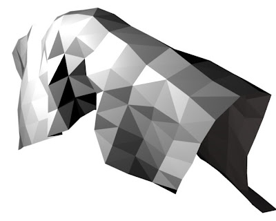
A series of models I have submitted for the final presentation :


Image 1 : The conceptual model done for week 8 submission


Image 2 : Conceptual model


Image 3 : Sectional model


Image 4 : Site model


Image 5 : Final presentation board


Sunday, June 12, 2011

WEEK 14 : RENDER THE INTERIOR IMAGES

Using Photoshop, I tried to render the interior images and work out with the specific spaces.


Image 1 : Main entrance showing walkway leading to the chill out area at the end of the building and ramp leading up to exhibition hall


Image 2 : Ramp leading to the exhibition hall at the first floor


Image 3 : The multipurpose open space


Image 4


Image 5 : Little bar for people to chill out

Friday, June 10, 2011

WEEK 13 : EDITING THE INTERIOR SPACES


Image 1 : Putting in light in the interior, testing on the brightness of the light


Image 2 : Trying to apply the 'smooth' application to the surface of the building but it doesn't work out well


Image 3 : Editing the interior of the building

Wednesday, June 8, 2011

WEEK 13 : Cross section the building

After confirming the final form of the building, I sectional cut the building in blender and bring it into Autocad.


Image 1 : cross section the building in Blender


Image 2 : Import the building into Autocad and trace it over.

Monday, May 30, 2011

WEEK 12 : WORK ON THE INTERIOR SPACES


After getting the form done in Blender, I tried to export the blender file into dxf file. By doing so, I will be able to work out the interior space in Autocad. I decided to use Autocad to extrude the floor since the form of the building is curvy and it will be very hard for me to work it out in Blender.


Image 1 : Trace the floor plan In Autocad


Image 2


Image 3


Image 4 : extrude the floor


Image 5 : perspective view of the ground floor area


Image 6


Image 7 : Interior done using the 'push pull' tool in Autocad


Image 8 : bring the interior from Autocad into Blender and work out the ramp in Blender


Image 9 : edit the ramp


Image 10 : edit the long ramp


Image 11 : edit the interior faces


Image 12: Interior images showing the seating area in the building


Image 13 : Top view showing the ramp moving from ground floor to first floor


Wednesday, May 18, 2011

WEEK 11 : Working on the interior spaces

I look for Zaha Hadid's building to get some inspirations for the interior spaces. Then, I come out with an idea to make the the building an exhibition on the first floor and the ground floor as a resting area.


Image 1 : the interior of 'The Opus' by Zaha Hadid


Image 2 : the interior of 'The Opus' by Zaha Hadid


Image 3 : Library & Learning Centre, University of Vienna perspective, Zaha Hadid Architects


Thursday, May 12, 2011

WEEK 10 : LASER CUT THE MODEL

Before working on the laser cut model, I cross section cut through the model and trace the outline of the model in Autocad.


Diagram 1 : import the sectional cut through of the building into autocad


Diagram 2: Trace the outline of the model using polyline


WEEK 10 : come out with list of SCHEDULE,finalise the form


In today's class, I come out with a schedule for the rest of the week.


Diagram 1 : Schedule from week 10 until week 14


Diagram 2 : Perspective view of the model


Diagram 3: Editing the facade of the structure (highlighted in red color)

Friday, May 6, 2011

WEEK 9 :Edit the Form using 'CLOTH CONCEPT'

The previous model that I did during the interim is too solid, hence I made up my mind to delete the solid plane I created in the facade. Instead I tried to use the cloth concept to develop a more fluid facade, so that the new facade and the building look as in they are a a whole piece of structure.


Image 1 : The original model without adding in the solid facade

I am going to develop a new facade from this original structure. A piece of 'cloth' will be applied on top of this structure.


Image 2 : cloth applied on top of the structure

The cloth looks solid without the application of the modifier, 'subsurf'.


Video 1 : animation of the cloth applied on top of the structure


Image 3 : the surface of the cloth is smooth now with the application of 'subsurf' modifier


Image 4 : front view of the facade with cloth enveloping the structure

I go through more animation, trying to look for a suitable facade by adjusting both the position the structure and the 'cloth'.


Image 5 : the cloth is placed at the site of the structure so that it flows horizontally through the model.

I realised it looks better when the cloth goes horizontally through the building. This is mainly because my model is lied horizontally. Hence, it is good to have the whole structure goes in the same direction.


Video 2 : animation done with cloth placed at the side of the model


Image 6 : 'cloth' extract out from the model, red color indicated the facade of the building.

This is the view captured when the cloth is being animated at frame 53. I kind of decided to have this view as the facade for the building. However, I tried to put the cloth in edit mode so that I can made some adjustment to the cloth but to no avail.

Thursday, May 5, 2011

WEEK 9 : PROJECT 2 : CONTEXTUAL AND SPATIAL PARAMETERS


Image 1 : top view of the rapid prototype model


Image 2 : front view of the rapid prototype model


Image 3: Back elevation of the rapid prototype model


Image 4 : Final presentation board for project 2

Wednesday, May 4, 2011

WEEK 9 : PROJECT 2 : CONTEXTUAL AND SPATIAL PARAMETERS


IMAGE 1 : AXONOMETRIC PROJECTION OF THE BUILDING


IMAGE 2 : HORIZONTAL CROSS SECTION OF THE BUILDING


IMAGE 3 : VERTICAL SECTIONAL CUT THROUGH THE BUILDING


IMAGE 4 : BACK VIEW OF THE BUILDING


IMAGE 5 : PERSPECTIVE VIEW OF THE BUILDING


IMAGE 6 : TOP VIEW OF THE BUILDING


IMAGE 7 : ENTRANCE LEADING TO THE BUILDING


IMAGE 8 : FRONT VIEW OF THE BUILDING


SOME OF THE TOOLS EXPLORED DURING THE PROCESS


IMAGE 9 : WATER SIMULATION TEST


IMAGE 10 : TRAIN SITTING ON THE PATH


IMAGE 11 : PERSPECTIVE VIEW OF THE TRAIN SITTING ON THE PATH

USE BOOLEAN TOOLS TO CREATE SLITS ON THE ROOF


IMAGE 12: CREATE THIN BOXES ON TOP OF ROOF, READY TO BE BOOLEAN INTO SLITS


IMAGE 13: ONE OF THE SLITS CREATE ON TOP OF THE ROOF


IMAGE 14 : PERSPECTIVE VIEW OF THE BUILDING


IMAGE 15 : PERSPECTIVE VIEW OF THE INTERIOR